30 June 2012

Acoustic properties of glass: not so simple

At Arup, working with different specialists creates many opportunities to learn from each other. Sometimes one forgets that engineers who know everything about dark matters as climatic loads in glass or intricacies of structural silicone may not have a clue about the acoustic performance of a window.

That's why these questions keep coming to my desk (remember I'm an incurable generalist in the façades world): what effect does glass thickness have in the acoustics of a double glass unit? Or what matters more in the acoustical performance of insulated glass: the thickness in a monolithic pane, the effect of lamination or the dimension of the cavity? Here you will find some graphical answers to these questions. As usual a number of hidden surprises will come out from the data mining.


Let us start by reviewing two concepts that are paramount to measuring glass performance against noise: loudness (in particular sound pressure level, the decibels thing) and frequency (the Hertz, not related to car rental)

1/ Loudness: sound intensity, sound pressure and sound pressure level

From physics to applied acoustics in buildings. No pain, promised. Loudness is an intuitive concept: a loud noise usually has a larger pressure variation and a weak one has a smaller pressure variation. Depending on what we are looking for - the cause, the effect or the perception of noise - we use different variables and units:

  • Sound intensity refers to the cause of noise (not of our concern, only of interest for acusticians). It measures energy flow at the source, so its unit is W/m2.
  • Sound pressure refers to the effect of noise as a wave impacting any given surface, that is, noise as energy being transfered through air. Not of our concern either, more for physicists. Its unit is the Pascal or N/m2 (1Pa = 1N/m2). 
  • Sound pressure level or SPL (here comes the fun) refers to the perception of noise in humans as it can be "read" by our ears. So SPL is what matters to us, poor construction buddies. For ease of numbering SPL is measured in decibels (dB). A dB is a dimensionless unit used to express logarithmically the ratio of a value (the measured sound pressure) to a reference value (the lower threshold of hearing). Decibels are used since sound pressure level expressed in Pa would be too wide. 0 dB (the lower threshold of audition for humans) equals 0,00002 Pa; whilst 140 dB (the upper human threshold or threshold of pain) equals 200 Pa. This is a range of 140 against 10 million. But logarithms are not "natural" to understand, so some examples will be of help.
Sound intensity, sound pressure and sound pressure level are obviously related, but they measure different things and they should not be confused. The table below, taken from the very useful Sengpiel audio webpage provides some tips for getting it right, at least conceptually:

SPL variation (left column) related to sound pressure (field quantity) and sound intensity (energy quantity)


Lessons from the table above:
  • A raise in sound pressure level (SPL) of 3 dB equals an increase in sound pressure (field quantity) of 1.414 times, and (everything else being equal) it comes as a result of doubling the sound intensity (the source of sound).
  • A reduction in sound pressure level measured inside a room of 10 dB equals a reduction in sound pressure of 3.16 times, and it comes as a result of dividing the sound intensity (noise generated on the outside) by ten.
A typical opaque façade (not glass) can have a sound reduction index (a reduction of SPL) of around 40 dB. This means that if the SPL measured at the street is 70 dB, inside the façade one would perceive only 30 dB. Up to here, just arithmetic. 

Now, if the sound reduction index of the façade could be raised from 40 to 43 dB, the perceived noise coming from the street would equal that of reducing the source of noise by half. Even more, if the façade could be acoustically improved so that its sound reduction index raised from 40 to 50 dB (difficult but it can be done), the perceived noise coming from the street would equal that of reducing the source of noise (sound intensity) by ten: ten times less cars in the street, ten times less people celebrating the victory of their football team outside.

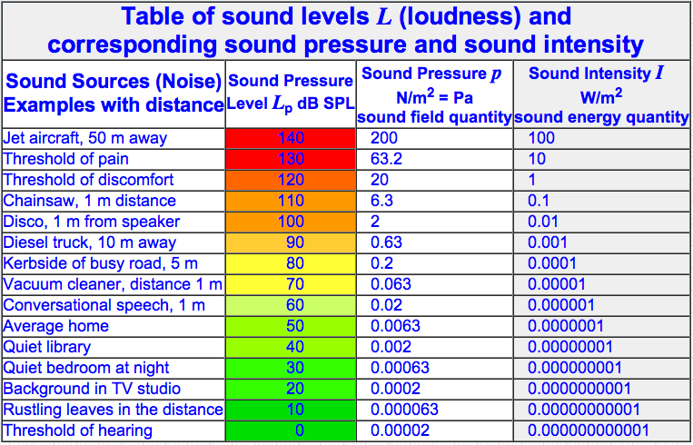
Expected sound pressure levels for different noises and their equivalent sound pressure and sound intensity. Source: Sengpiel Audio.


We got the point: sound pressure level measured in dB (sometimes indicated as dB-SPL) is critical for architectural physics - a small variation can make a lot of difference. But loudness (sound expressed as pressure variation) is not the only story. Noise - what we want to avoid inside our buildings - is the mixture of sounds of different "quality", some are bass, some are treble. Is our façade or our glass pane capable of stopping each of these "noise qualities" in the same percentage? Could an envelope act as a barrier for bass and a filter for treble? What do bass and treble have to do with noise?

2/ Frequency of sound

Sound is the quickly varying pressure wave travelling through a medium. When sound travels through air, the atmospheric pressure varies periodically (it kind of vibrates). The number of pressure variations per second is called the frequency of sound, and it is measured in Hertz (Hz) which is defined as the number of cycles per second.

Graphic representations of a sound wave. (A) Air at equilibrium, in the absence of a sound wave; (B) compressions and rarefactions that constitute a sound wave; (C) transverse representation of the wave, showing amplitude (A) and wavelength (λ). Source: Encyclopaedia Britannica.


The higher the frequency, the more high-pitched a sound is perceived. Sounds produced by drums have much lower frequencies than those produced by a whistle.

The unit of frequency is the Hertz (Hz). For a sound vibration to be audible to human beings the object must vibrate between 20 and 20,000 times per second. In other words the audible sound has a frequency of between 20 and 20,000 Hz.

High-pitched sounds (treble) have a frequency much greater than bass sounds. The treble frequency ranges between 2,000 and 4,000 Hz while the bass range from 125 to 250 Hz. 

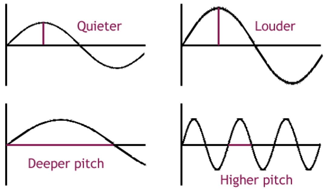
Above: measure of loudness (wave height). The higher the louder.
Below: measure of frequency (wave length). Bass sound has long waves, treble has short waves.


Bad news: frequency and loudness are interrelated in the human ear. The range of 20 Hz to 20,000 Hz is called the audible frequency range - we know this already. But the sounds we hear are a mixture of various frequencies, and we don't perceive all of them with the same clarity. Let's see what the implication of this is.

The entire audible frequency range can be divided into 8 or 24 frequency bands known as octave bands or 1/3 octave bands respectively for analysis. An octave band is the band of frequencies in which the upper limit of the band is twice the frequency of the lower limit. Any particular sound or noise can be represented as a number of 8 (or 24) sound pressure levels in the frequency bands, as illustrated by the diagram below.
A real sound shown as a combination of different sound presure levels, one per each of the 24 frequency bands. Column width: 1/3 octave band (24 in total). Column height: SLP at each frecuency band, measured in dB.


The response of the human ear to sound is dependent on the frequency of the sound. The human ear has its peak response around 2,500 to 3,000 Hz and has a relatively low response at low frequencies. Hence, the single sound pressure level obtained by simply adding the contribution from all 1/3 octave bands together will not correlate well with the non-linear frequency response of the human ear.

This has led to the concept of weighting scales. The following diagram shows the "A-weighting" scale:

Reduction of SPL (in dB) at frequencies below and above 2000 to 3000 Hz to reflect the frequency response of the human ear.

In the "A-weighting" scale, the sound pressure levels for the lower frequency bands and high frequency bands are reduced by certain amounts before they are being combined together to give one single sound pressure level value. This value is designated as dB(A). The dB(A) is often used as it reflects more accurately the frequency response of the human ear. 

Other, less used weighting scales, are dB(B) and dB(C). The decibel C filter is practically linear over several octaves and is suitable for subjective measurements at very high sound pressure levels. The decibel B filter is between C and A. The three filters are compared below:

Noise filtering at different octaves of frequency applying decibel filter scales A, B or C.


That was enough for theory. Let us now see how all this affects the performance of glass as a real acoustic barrier.

The four hand-sketched graphs shown here below are all taken from the first edition of a great book called "Detailing for acoustics", written by Peter Lord and Duncan Templeton. There are three editions by now and I highly recommend buying one if you are an architect interested in acoustic issues applied to buildings.

3/ Glass thickness effect

The sound attenuation of any material depends on its mass, stiffness and damping characteristics. With a single glass pane the only effective way to increase its performance is to increase the thickness, because stiffness and damping cannot be changed. The sound transmission loss for a single glass pane, measured over a range of frequencies, varies depending on glass thickness.

Thicker glass tends to provide greater sound reduction even though it may actually transmit more sound at specific frequencies. Every glass pane thickness has a weak frequency value; that is, a frequency for which that glass is less 'noise absorbent' than for the others. That value is known as critical frequency. See the graphic below:

Sound reduction (in dB) measured at different frequency bands for glass panes of different thickness. Source: Detailing for Acoustics, Lord and Templeton.


A 4 mm-thick glass is rather transparent (poor attenuation measured in dB) for high frequencies at the range of 3500 Hz; 6 mm-thick glass is poor for frequencies around 2000 Hz; and 10 mm-thick glass performs bad at 1300 Hz. The higher the mass the less of a problem critical frequency appears to be: 25 mm-thick glass has no weak point as it can be noted from the graph above.

An insulating glass unit built with two panes of the same thickness experiences the issue of critical frequency: it is said that the two panes vibrate (resonate) together at that frequency, thus reducing the glass overall acoustic performance.

For this reason we recommend using different thickness in a double glass unit. A 6-12-4 mm glass will absorb more sound at high frequencies of 2000 Hz (claxon noise) than a 6-12-6 mm glass, in spite of having less mass. On the other hand, at lower frequencies between 125 and 250 Hz (traffic noise) this is not the case: a 6-12-6 mm glass reduces sound more effectively than a 6-12-4 mm glass. At low frequencies sound attenuation is directly proportional to mass.

4/ Laminated vs. monolithic glass

A laminated glass will attenuate sound transmission more than a monolithic glass of the same mass. See the graph below:

Sound absortion of monolithic (solid) glass compared to laminated glass with the same mass. Source: Detailing for Acoustics, Lord and Templeton.

A laminated glass of 2+2 mm reduces sound at high frequencies considerably more than a monolithic glass 4 mm-thick (that's 8 to 10 dB of additional attenuation). Why? because the critical frequency effect disappears due to the sound damping provided by polyvinyl butyral (the soft interlayer used to permanently bond the glass panes together dissipates energy by vibration). The same applies to the 3+3 mm laminated against the monolithic 6 mm. In contrast, at low frequencies (traffic noise) the effect of butyral is less pronounced, although it is still positive (about 2 dB increase).

5/ Air cavity effect

Surprise: a standard double glazed unit does not reduce sound transmission much more than a monolithic glass. What matters is the thickness of the air space between glass panes, but only for really wide cavities.
Effect of air space width on the acoustic performance of double glazing. Source: Detailing for Acoustics, Lord and Templeton.
The acoustic attenuation of a 6-12-6 mm glass is generally superior to that of a monolithic 6mm-thick glass, but only by 2 or 3 dB, and still there may be low frequency bands where the DGU performs worse. Of course if we compare a 6 mm-monolithic with a double glazed 12-6-10 mm, the sound reduction is much better at the double glazed unit.

What really matters is the width of the air space, not the small one found at double glazing but the one of a double skin. The ideal cavity width to boost sound attenuation is 200 mm. For widths less than (or greater than) 200 mm the effect is less noticeable (although a wide air space will always perform better than a narrow one). A double glazing with 10 mm air space performs almost like a 20 mm airspace.

6/ Combined air cavity & glass thickness effect

The conclusion comes in the last graph: a combination of large thickness, different one between the two panes and wide air space distance (even better if we use laminated glass) provides the maximum noise attenuation. We can reach up to 45dB.
Combined effect of glass thickness and air space on the acoustic performance of double glazing. Source: Detailing for Acoustics, Lord and Templeton.


To achieve this with a conventional double glazing width (about 28-35mm only) we have to employ an acoustic interlayer or a sort of resin between two panes in a laminated glass combined within a DGU. These acoustic interlayers or resins dissipate sound waves much more than two or three PVB interlayers as in a typical laminated glass. Some brands of enhanced acoustical laminated products are:
SGG Stadip Silence effect as part of a double glazed unit. Other brands perform similarly. By the way, the scale below is not frequency but loudness (it measures dB). Taken from Saint Gobain Stadip Silence brochure.

What about the effect of using argon or krypton instead of air? In theory, a higher density gas in the space between panes should have a positive effect on acoustical performance. Comparison testing of standard symmetrical insulating units indicates though that common gases as argon have virtually no increased effect on sound attenuation ratings. While some improvement was noted at some frequencies, resonance effects actually became more pronounced.

7. Some useful values

Rw index: The Rw index or sound reduction index (expressed in decibels) measures, in just one number, the acoustic performance of a specific glass unit. The higher the Rw index, the better the level of acoustic insulation offered by that glass composition. The Rw index of ordinary double glazing is around 29 dB whereas a good acoustic interlayer offers an Rw index of around 50 dB.

Rw is a single figure rating for the airborne sound insulation of building elements (not just glass). It includes a weighting for the human ear and measures actual sound transmittance. Rw is measured in a laboratory, not on site (the site-measured equivalent value has the Egyptian denomination of DnT,W). The Rw value is merely an average simplifying mutual comparison of various building components. That can be confusing some times. Two glass units can have the same Rw index while one of them performs well at low frequencies and bad at high ones, and the other one performs just the opposite.

C and Ctr factors: To slightly avoid this issue two spectrum adjustment factors: C and Ctr, have been added to modulate the Rw average. For sound waves featuring high frequencies, the factor C is added to the Rw value. For lower frequencies, factor Ctr needs to be added. The acoustic behaviour of a building component is hence defined by three numbers: Rw (C, Ctr). A building component with the values Rw (C, Ctr) = 40 (-1, -4) provides an average insulation performance of 40 dB. For higher pitched sounds the sound insulation is lessened by 1 dB (39 dB) and for lower pitched sound sources it is lessened by 4 dB (36 dB).

The table below, extracted from Saint Gobain, helps showing how these three numbers apply to different laminated units with acoustic interlayers:

Sound reduction index values for several laminated glass units with acoustic interlayers. The thickness shown at the right column is the total one. 13 mm means 6 mm + 6 mm + 0.8 mm interlayer. Taken from Saint Gobain Stadip Silence brochure.

C takes into account medium and high frequency noise sources such as TV, music, loud conversations or aircraft noise a short distance away. Ctr takes into account medium and low frequency noise sources such as urban traffic noise or aircraft noise a long distance away.

Pink Noise:  Expressed in dB(A), this is an assessment of the sound insulating properties of a building material over specified standard frequencies, which represent general activity noise when equal levels of power are applied at each frequency. So, in pink noise each octave carries an equal amount of noise power. Funnily: the name arises from the pink appearance of visible light with this power spectrum.

Ra:  Ra is the abbreviation for the sound reduction index when the spectrum adaptation term C is applied to the single number weighted sound reduction index (Rw), using pink noise as a sound source.

Ra,tr:  Ra,tr is the abbreviation for the sound reduction index when the spectrum adaptation term Ctr is applied to the single number weighted sound reduction index (Rw) using pink noise as a sound source.

So far so good. Acoustic performance of glass should now be less of a dark matter for us. But this is not all: remember that detailing to achieve a proper air tightness between glass and frame will always be required! Loose gaskets can severely harm the best glass selection for acoustics...

28 May 2012

Sydney Opera House: decoding the glass walls

Utzon's sketch of the Sydney Opera House. The Red Book, 1958.
First, a confession: I've never been to Australia. Is it possible to 'decode' a complex element of the Sydney Opera House as the external glass walls without having ever visited the building? The obvious answer is no, but one doesn't lose much with trying.

Jorn Utzon
Then, there is some consolation in the fact that Jorn Utzon himself never saw the glass walls as they are now - he didn't even take part in their final design. This is the second most important feature of the facade of the Sydney Opera House - after the concrete shells of course - and it is not an Utzon design at all: Utzon left the site in 1966 and the glass walls were designed and built bewteen 1970 and 1972.

In this post we will not deal with the concrete shells or the precast enamelled porcelain cladding of the shells. Our focus are the glazed walls located at both ends and long sides of the three main buildings above the podium: the Concert Hall, the Opera Theatre and the Restaurant.

Glazing of the Concert Hall north end, 1972.

Many questions arose when I started digging: are the glazed walls at least partly Utzonian? Who were their designers? Was it a smooth process - since the Danish architect was not there any longer - or was it another nightmare within the general conundrum of the job? And finally, is there anything we can learn from the Sydney Opera House glass walls, now that we celebrate 40 years after their conclusion?

The glass walls during the competition and first stages of design.
Let's start at the beginning. It is November 1956 in Hellebaek, Denmark. Jorn Utzon, a young architect (38 at the time) has spent all his spare time during the last six months working at the design of an Opera House for a competition in Sydney, Australia. He has of course not visited the site - it would be too strenous and expensive an effort. His main ideas for the design are already defined: the unifying podium, the decision of splitting the opera hall and the theatre in two parallel buildings plus a smaller one housing a restaurant, a number of concrete shells flying above the three volumes.

Competition section drawn by Utzon, 1956.


Natural light is not a critical requirement for an opera house; concerts and theatre plays happen mostly at night. But views of the Sydney bay are magnificent at the point where the buildings will be located, and Utzon's design gives predominance to the two short ends of the main buildings: one edge overlooking the bay, the other receiving visitors from the city. What did Utzon imagine for those large gable ends behind the shells? Around the end of the competition (see above) he quickly draw a longitudinal section showing vertical glass walls hanging from the outer shells and suddenly twisting out to become almost horizontal glazed canopies. At one side (north, overlooking the bay) the glazed canopies cover the space of the back foyers. At the other side (south, looking to the city) they are part of the entrance space receiving the visitors.
SOH - Plan, 1957. North is at the left side. Top: Theatre. Down: Opera and restaurant.

SOH - South view, first model 1957. From left to right: restaurant, Opera and Theatre buildings.
SOH - North view, first model 1957. Left: Theatre; right: Opera Hall building.
Jump to late spring 1957. The competition had been awarded on January that year and Utzon had come up as the winner. He is rushing with the preparation of additional drawings and a model (the first one) to take with him for his first visit to Sydney. The north shells are now taller, and the south ones shorter.

The model (see the two images above, south and north sides) has a first visualization of the glass walls. They look like a simplified version of the competition scheme: there are no horizontal glazed canopies, and the upper part of the glass walls is covered with what looks as horizontal louvres. Remember we are in Australia; midday sun shines at the north side and louvres here appear on both sides. This proposal was not going to last.

Cover of the Red Book, prepared by Utzon in 1958.


Platform level with zig-zag vertical glass walls, 1958.
Further jump, now to spring 1958. Utzon has just completed a preliminary summary of the project at his office in Hellebaek, before returning to Sydney to meet with his client for the second time. The design and a supporting text are encased in an elegant publication with a vermillion cover: it would become known as the Red Book.

The design for the glass end walls adopts a different configuration: they are now zig-zagging in plan and vertical in section, looking like a folding screen (see plan above and section below). This makes sense from a structural point of view because the different folded planes stiffen one another against wind loads. A second look at the longitudinal section below explains why these glazed elements are so stiff: the roof shells in the Red Book are still rather low, thus requiring an edge support at the glass walls. So these woud have to incorporate some kind of steel mullions transmitting the roof loads down to the podium.

Longitudinal section of the Concert Hall, Red Book 1958. Notice the folding screen glass ends.
The elevations show the glass walls divided in rectangular pieces with discontinued horizontal transoms. The longitudinal section deals (rather unsucessfully) with one of the future problems of the glazed walls: how they connect with the curved inner side of the shells. A vertical, folding screen plan as proposed here would obviously make this connection a nightmare.

West elevation of the Concert Hall, Red Book 1958. Transoms are located at different heights; the folding screen at left masks roof-supporting columns for the north shell.


The proposal for the glass walls shown at the Red Book (the third version of this element) would have no continuation, as the previous two. It is clear that Utzon, in the period between 1956 and 1962, was more interested in developing first the general concept, then the podium and finally the shell roofs of the Opera House. The glass walls, as many other important design elements, had to wait. This design process so dear to Utzon - progressing element by element - would prove to be a crucial mistake and was part of the crisis that would eventually force his resignation from the project in 1966.

The glass walls in Utzon's project for Stage II
It soon became clear that the whole Opera House process would take a long time to design and build. The client, the architect and the engineers agreed in splitting the design and construction process in three stages: Stage I for Podium; Stage II for the roof shells and Stage III for glass walls plus interiors.

The construction of the Sydney Opera House started by the podium in March 1959, based on the Red Book designs with some modifications, finally approved in April 1958. As the construction of the podium progressed, Utzon and the engineers of Ove Arup and Partners continued to progress on the roof shells design, both in Hellebaek and London. The geometry of the shells presented in the 1958 Red Book was based on a parabola. Since this presented several engineering and construction problems a long period of proposals ensued, until in the autumn of 1961 Utzon came up with the proposal of using a sphere as the geometry for the surface of the shells. This was supported by Ove Arup and allowed the engineers to finally produce calculations and construction drawings for the shells in 1962 - 63.

Cover of Utzon's Yellow Book, dated 1962.
In the spring of 1962 Utzon returned to Sydney in order to present the Stage II architectural diagrams along with Jack Zunz, head of the engineering team in Ove Arup and Partners. Utzon's presentation - the next one after the Red Book - would be called the Yellow Book because of the colour of its cover.

In the Yellow Book, unlike for years ago with the Red Book, Utzon and his team present for the first time a well-thought proposal for the glass walls, at least in geometrical terms. Now the edge shells, based in a spherical shape, are higher and more pointed than the first shells. The now self-standing superstructure no longer required the complementary support considered in the Red Book four years earlier. The glazed facades could become the light membranes first envisaged during the competition: curtain walls, suspended under ogival arches, formed by blades of glass mounted in slim frames. In a letter from 1965 Utzon explained (as quoted by Françoise Fromonot in 'Jorn Utzon. The Sydney Opera House'):
"The problem that faced me was to create a glazing system sufficiently flexible to make up the irregular overall shape and have sufficient strength to resist the wind loads imposed over such a vast area".
And he continued:
"Our early attempts to use composite structures of concrete and steel or bronze were too complicated and too rigid. The answer was to be found in a simple geometrical system consisting of a series of glass panels of modular size held between flexible mullions which can be adjusted to any shape and portion as required". 
Utzon selected tubular plywood as the preferred material for these mullions, and he abandoned the sheer verticality of his previous solutions to embrace articulated membranes, "like the wings of a bird".

Glass wall principle from the 1962 Yellow Book.
Reference image for the new mullions idea: sea bird, picture by Emil Schultess.
Utzon illustrated this metaphor with an image of a seagull in flight. The glass walls now curved out in overlapping sections from top to bottom, from vertical at the summits of the vaults to near horizontal above the platform. At the lower end, their tales formed transparent canopies over the glass doors that provided access to the foyers. The folding mullions implied the absence of a dead-loading mission as well as eliminating reflections in the glass.

The images below are taken from the Yellow Book and show the application of the plywood mullions to the north and south glass walls.

Side elevation and plan of the northern glass wall framing. Yellow Book, 1962.


Section and front elevation of the northern glass walls. Yellow Book, 1962.


Development of the glass walls by Utzon during Stage III
In March 1963, a year after the presentation of the Yellow Book, Utzon moved to Australia to live there with his family. Construction of the Opera House roofs was well underway and he was occupied - finally - developing his proposals for the glass walls and the interiors.

For both elements Utzon had decided to use innovative plywood technology. It may seem a little incongruous to develop timber profiles as structural elements for immense glass walls, but it followed a joint research undertaken by the architect with the Australian company Ralph Symonds Ltd, experts in reconstituted wood for industrial use. Ralph Symonds, a short man but a visionary industrialist, set up a vacuum bagging process and very large presses so that plywood could be made in 50 foot long sheets (about 18 metres), which was at the time an enormous length of plywood. Utzon saw this and realised that by using Symonds' vacuum bagging process he could achieve large sections in plywood spanning long distances. These sections were going to be the lining systems of the small theatres underneath the podium of the Opera House and the corridors. And they were the right material for the mullions at the glass walls as well.

Plywood mullions as standard elements - Architect's models, end of 1964.

The mullions were to be built up bonding seven layers of 13mm white Soraya pine plywood sheet into 600mm deep x 90m wide sections. The layers could be stepped to accomodate all mullion configurations. On either side of the timber mullion the external layer would be curved to form a U-shaped channel to which the glass would be fixed by a normal screwed-on clip system. Finally a U-formed cover piece would enclose the outer mullion front. To resist external weather conditions these cover pieces were going to be finished in hot-bonded bronze sheets.

The mullions were to be prefabricated and then assembled on site, like a Meccano set. The result, to Utzon satisfaction, combined the design of pieces suited to their role with the accuracy of industrial craftmanship.

Plan section and model from 1964 showing the standardisation solution for the south walls.

Model dated end of 1964. Concourse view with plywood mullions, south side.

View from the harbour (north), model 1964.
The drawings prepared by the architect's team on site between 1964 and 1965 show all glass walls in the same grid of 1.2m wide, reflecting the dimension of the paving slabs of the platform, visually conveying this dimension up to the peaks of the vaults. In the last drawings from 1966 the glass width has been reduced to 91cm (3 feet). Glass would be laminated for safety reasons, the panels being specified in commercially available dimensions.

On the last model produced under Utzon's supervision - dated early 1966 - the glass walls have a more vigorous quality; transoms have been totally suppressed and the mullions fall directly onto the bottom platform. The mullions are thin and deep: viewed from the side the facades would be perceived as an opaque layering (see the two images below).

Model from early 1966, section of the Major Hall outlooking the bay. Mullions here come down to the foyer floor.
Model from early 1966, North view from the harbour. 
A recent view of the last section model prepared under Utzon's supervision in 1966.
Was the last of Utzon's ideas for the glass walls feasible from a technical point of view? Jack Zunz, the engineer from Arups on site, always said no. If we apply the knowledge of our day to this plywood mullion concept the probable answer is once again negative. Because of a number of reasons: spans were huge, there was no lateral stifness, geometry was not solved yet (glass would have to assume a tri-dimensional surface), and it is doubtful that bonded plywood from the sixties would have resisted for a long term in a maritime environment.

In any case the question above is irrelevant. The new Australian government was willing to get rid of Utzon and minister for Public Works David Hughes refused to approve the plywood mock-ups for the auditoria ceilings. This, among other issues, forced Utzon to present a letter temporarily withdrawing as the Opera House architect on 28 February 1966, resignation that was immediately accepted. A new period was about to start for the glass walls design, now and forever beyond Utzon's command.

Final design Stage III - rethinking the glass walls
On April 1966, minister Hughes announced the three new architects appointed to complete the Opera House: Peter Hall, 34, design architect; Lionel Todd, 36, supervision; and David Littlemore, 55, documents. Ove Arup and Partners would remain as project and site engineers.

Stage I of the works, including the steps, concourse and platforms had finished in January 1963. Nine months after Hall, Todd and Littlemore had taken charge, in January 1967 the last tile lid was lowered into position and the roof shells - including their cladding - were complete, ending the Stage II of the works.

When they took over the design development of Stage III, Hall, Todd and Littlemore were to be busy with two questions : the seating capacity of the Opera Hall (later downgraded into a Concert Hall due to lack of space) and acoustics. More than two years after the new architects had taken charge the government approved the new programme, and site work on Stage III commenced in 1969.

Code names for the different glass walls designed between 1967 and 1970. Image taken from Harry Sowden, 'Sydney Opera House glass walls', published in 1972.

The concept of the scheme finally selected for the glass walls by Peter Hall with assistance of the Arups team, a continuous glass surface enclosing a steel structure, dates from mid-1967. This concept was developed for more than two years and involved much research into a wide range of façade materials and techniques.

It is quite easy to undervalue the work taken by Peter Hall and the team of architects and engineers that were to finish the Opera House after Utzon's dismissal. I find that a very unfair position, at least for the glass walls part. As David Croft, Arups design engineer dealing with the glass walls development would say at the time:
"The glass walls are an epitome of the problems of the whole of the Opera House (...). Every day I find it more complicated than it was before. The more you do the more there is to do"
Michael Lewis' hands drawing the glass walls in the air, and David Croft at his office on site. 
The last part of this post will demonstrate up to what point the final glass walls solution owes to the previous concepts designed by Utzon and where it departs from those to make the whole thing possible. I have based my information on two sources, not easy to find today, both bearing the same name: 'The Sydney Opera House glass walls'. The first is a paper written by David Croft and John Hooper, engineers from Arup, published at The Arup Journal in October 1973. The second is a book written by photographer Harry Sowden with contributions from Peter Hall, David Croft, John Hooper, Bob Kelman and Michael Lewis, all engineers from Ove Arup and Partners on site, and self-published in 1972. Most of the black and white images shown from here below come from this book.

The three buildings as built, looking south: Restaurant (left), Concert Hall and Theatre Hall. 

Theatre Hall: southern glass wall seen from bottom up.
Providing the final concept
Despite much technical discussion, investigation and studies, no detailed technical solutions were available for the glass walls at the time of Utzon's dismissal from the project in February 1966. But at least the architect's requirements could be clearly identified as follows:
  1. All the glass walls throughout the Opera House are to be read as one family, with a similar structural layout.
  2. The structure shall be as clean as possible, with bracing kept to a minimum if not eliminated.
  3. The mullions shall not be read as supporting the shells: the glass walls shall look as hanging from the shells instead.
  4. Mullions shall be as thin, continuous fins throughout the glass walls.
  5. Below the roofs there shall be as little visual obstruction as possible.
  6. The mullion frames shall be constructed as a series of constant-section units, marking by their position a continuously varying shape across the width of the glass walls.
Peter Hall from Hall, Todd and Littlemore begun working in the glass walls at the beginning of 1967. The material favoured by Hall for the mullions (probably with some positive comments from the Arup engineering team) was steel instead of plywood. But this still required a different material or protection for the outer side of the mullions, exposed to maritime conditions. Concrete was investigated but with unacceptable aesthetic results. The time had come to review the whole philosophy of the glass walls. This was done via a workshop at the London office of Ove Arup & Partners. Peter Hall was there from the architects, and Jack Junz, Michael Lewis and Yuzo Mikami from Arups, with some participation from Ove Arup himself.

From left to right: Michael Lewis, Ove Arup and Jack Zunz on site during Stage II construction.

Point 3 above presented a key isue to solve: because of the differing geometry of the roof and podium structures the mullions had to be bent outwards in vertical section, thus achieving a usable plan area at the bottom, greater than that covered by the shells. And to make the mullions look like hanging from the shells it was necessary that they were effectively fixed at their top edge and then fall in vertical down to a certain point. This lead to a geometry for the two most complex walls, those overlooking the harbour at the Concert and Theatre Halls (A4 and B4 respectively, see above plan with name indications), that would be the combination of a cylinder and two cones, all with their axis located in one same vertical line. See the image and picture below for clarity. 
The final geometry of glass walls A4 and B4 (those overlooking the bay at north elevation)

The top part of the glass wall belongs to a cylinder, it then intersects with an inclined cone, and this one intersects again with a lower cone, resulting in an opening-out section as it moves down.

Northern glass walls as built: B4 to the left (Theatre) and A4 to the right (Concert Hall).

New principles incorporating some of the ideals expressed by Utzon were developed and refined. The choice of material, method of fixing and sealing, all required solutions which had to be worked out from first principles. The task of fitting a suitable glass wall shape into an already completed structure without any plane surfaces demanded much study and effort. Many proposals were tried and rejected throughout the design period, which lasted from September 1967 to May 1971. But in the end the glass walls were eventually built.

Glass wall A4 (north Concert Hall). Elevation with and without glass.

Glass wall A4. Plan with and without glass. Notice the horizontal bracing at the central axis.
Glass walls A4 and B4
With an agreed concept, the detailed desig of the glass walls was carried out in parallel with their construction. Design work was initially concentrated on wall A4, bearing in mind that the details as they evolved would also have to apply to the other walls.

Glass wall A4. Side elevation
The choice of glass was a chapter in itself. The main requirement was for a safety glass that could be cut to shape on site. Toughened glass was thus rejected and laminated glass was chosen. At that time these was little information available to the use of laminated glass in buildings, so a research and testing programme was put in place. The laminate finally selected consists on a 12mm layer of clear plate or float glass and a 6mm layer of bronze tinted glass, bonded together with a 0.76mm double interlayer of clear polyvinyl butyral. The intention was to avoid the image of 'green glass' that would have come out if 18mm clear laminated had been selected, plus the advantage of solar shading provided by tinted glass in the highly exposed north orientations.

Pot-cast glass (left) and float glass (right): manufacturing the two lites of the laminated piece.

The precise tint (called demi-topaze) was created by a glass supplier in France and applied through a process named pot-casting, then the 6mm tinted lite was laminated to a 12mm clear lite in a different factory near Paris and finally the laminated was pre-cut and shipped to Sydney. The maximum sheet size required on site was approximately 4.0m by 2.1m.

Glass sheets size (left, wall A4) and example of a cutting list made in 1970

Glass support system
In the main surfaces each glass sheet is supported along its two 'vertical' sides by glazing bars, and the top and bottom horizontal joints are filled with silicone rubber sealant. The glazing bars were extruded from manganese bronze and in their standard form consist of a T-section and a cover piece screwed on after the final positioning of the glass. The combined sections act together as an I-section. The glazing bars follow the lines of the structural mullions inside and each glass sheet is held vertically by two steel pins projecting from the flage of the T-piece.

Glass fixing bracket conecting the T-shape (upper right) to the steel mullion (bottom right)

The glazing bars are attached to the structure by means of fixing brackets at roughly 0.9m centres. These brackets had to be adjustable to accomodate the geometrical variations in angle and distance between structural mullion and glass. The fixing proved to be quite a complex piece of machinery and advice was sought from the aircraft industry. The design was developed in conjunction with Hawker de Havilland Pty and the 2,300 plus fixings were manufactured by them. The material used was aluminium bronze which offered strength together with resistance to corrosion and fatigue.

The mullion structure
Steel was chosen for the main mullion structure on account of its strenght and stiffness. The standard mullions were fabricated from two parallel 90mm diameter tubes at 530mm centres joined by a 6mm plate web. This section had the advantage that the geometry could be solved along the centre line of the outer chord and standard connection details could be developed that would apply to the whole range of orientations that would occur.

Mullion and glass structural details as built, Sydney Opera House.

One of the critical details of each of the walls was the method of connecting the mullions to the shells at their top edge. The position of cables in the pre-stressed ribs prohibited any form of drilling into the rib to make a fixing. Luckily, during the design of the shells certain ribs had been chosen to support the glass walls, which were strengthened and had extra holes cast into them. These holes did not coincide with the position of the mullions and it as therefore decided to cast on to the rib a strip of in situ concrete.

Mullions top fixing to the corbels, and installation of ties between mullions.

No two corbels are identical, nor is the interval between corbels constant, and in situ concrete was therefore the most suitable material.

Process of fixing mullions on site with scaffoldings. A4 wall.

Coonection between top and bottom mullion
The mullions were fabricated in two sections, one for the top cylinder, the other for the upper and lower cones. The upper sections are bolted to the corbels and tied back at the bottom by struts to the rear wall of the auditorium. The lower sections are bolted to the upper sections and are supported at the lower end by trusses suported, in turn, by V-colums on the podium.

The result of this process was to liberate a wide inner space at the floor level, both at the entrance and at the back side of the auditoria, thus providing a much required space for internal circulation, as can be seen in the image below. I am still impressed with the lightness of the structural concept considering the large spans and the loads. A real feat!

The foyer at A4 (Concert Hall) seen from inside. The V-columns support a line of flat edge trusses where the mullions sit.

Sealing and waterproofing - more problems
There is no space here to detail the research conducted by John Hooper from Arup on laminated glass under sustained load, the geometrical calculations and structural analysis using computer programmes - the first ones on facade elements that I have notice - or the clever method devised for shaping laminated glass sheets to fit the varied dimensions. All this can be read at the Arup Journal article from October 1973.

My last note will be on a nowadays quite standard detail, silicone sealing, that was rather new at the time and created much confusion when problems arose during glass installation. With much of the glass inclined to the almost horizontal and located above public spaces, it was particularly important that the walls should be completely watertight. Use of the best available type of sealant was essential, and silicone rubber by Rhône-Poulenc (translucent type) was selected for this purpose.

Installing glass with suction cups and a crane. 
The choice of silicone rubber was really dictated by the presence of the horizontal glass-to-glass butt joints. These joints are directly exposed to the atmosphere and silicone rubber, besides having an excellent adhesion to glass, has a high resistance to ultra-violet radiation and other weathering agents.

Silicone rubber, being a one-part sealant, is relatively easy to apply; compressed air guns were used on site as the image below shows. However, it is crucial that the substrates have to be cleaned and prepared to quite stringent standards.

Silicone being applied to the extruded bronze T-joint before installation of the glazing bar.

Approximately a month after the first sealing was complete in the A4 wall, it was noticed that the sealant was separating from the bronze glazing bar. The most likely reason appeared to be poor preparation of the bronze work, or atmospheric contamination prior to sealing. The faulty material was cut out, a series of site tests conducted and the areas resealed. It soon became evident that the problem was much more serious than anticipated: it was almost impossible to achieve a permanent adhesion of silicone to bronze which could withstand water immersion.

The manufacturers were consulted, other primers were tested and gradually a successful technique was evolved. The problem appeared to be that the silicone joint as designed was too deep in relation to its width. The volume of silicone on the joint was excessive in relation to the free surface area from which acetic acid - generated during the curing - could disperse. The acetic acid was able to attack the bronze through the primer, and the product of this action dissolved out when the joint was immersed.

Cleaning and protecting the joints from dust prior to silicone sealing.
The cross section of the joint was changed to allow a greater surface area of sealant relative to the volume, to facilitate dispersion of acetic acid, and the method of clamping the cover strip down on to the sealant was introduced. More time also had to be allowed for curing of the primers before the silicone was applied and much more time given for the silicone to cure and the generated acetic acid to disperse, before the cover strip was placed.

It also proved important to protect the joint from water until curing was complete. To do this, strips of polythene were sealed down to the glass, covering the joint, and they remained there until the scaffolding was removed. The joint as finally perfected remained watertight, quite independently of adhesion between silicone and bronze, as initially expected...

Final code
My intention when I started this long post was to answer a number of questions. The answers should be clear by now:

  • Are the glazed walls at least partly Utzonian? Yes they are: a look at the competition section from 1956 is not too dissimilar to the final design, and Utzon's main requirements were met by Peter Hall and his team. 
  • Who were their designers? A bunch of architects and engineers, but the main credits should go to Hall, Lewis, Croft and Hooper. 
  • Was it a smooth process or was it another nightmare within the general conundrum of the job? Croft provided an accurate answer for this, quoted above. 
  • And finally, is there anything we can learn from the Sydney Opera House glass walls? Our old man, Ove Arup, provided a general answer that fits here perfectly well: "We have realised that only intimate integration of the various parts or the various disciplines will produce the desired results". Amen.

Ove Arup
As usual in these posts, a last paragraph should go to leave track of the suppliers, manufacturers and contractors involved in the building of the Sydney Opera House glass walls. Here they are:

  • Main contractor, M. R. Hornibrook Pty Ltd. 
  • Steelwork for the glass walls, J. W. Broomhead Pty Ltd. 
  • Metalwork and installation, Permasteel Pty Ltd. (yes, these are the guys that later would join the Italian company Isa to become the world-known façade contractor Permasteelisa). 
  • Fixings, Hawker de Havilland Pty Ltd. 
  • Sawing machinery and glass handling equipment, Quick-steel Engineering Pty Ltd. 
  • Glass cutting and installation, VASOB Glass Pty Ltd. 
  • Bronze extrussions supply: Austral Bronze Crane Copper Pty Ltd. 
  • Glass supply, Boussois Souchon Neuvesel + Société Industrielle Triplex. 
  • Sealant: Rhône-Poulenc.


If all suppliers and installers kept their contribution to the construction of the Sydney Opera House with great pride, Permasteelisa is probably the company that took it more deeply. Their company logo (left) is a schematic elevation of the A4 gable end. Massimo Colomban from Permasteelisa likes to mention the new technologies applied in large scale in this job for the first time. He is probably right on two of them: these were the first large suspended glass walls and laminated glass was used here in large - and in deep - for the first time. Colomban adds that this was also the first example of extended use of structural silicon glazing. This is not right as we have seen; glass is mechanically fixed at the large sides and it is bottom supported on pins. He probably has been told about the conundrum of the silicone application and how some lessons were taken from it; but complex as it came out this was just weatherproof sealing, not structural sealing.

I can't resist the temptation of adding a selection of images about the details, construction or final impression of the glass walls, that I found interesting but have not been able to place in the text above. Here they are.

Installing the inclined glass pieces overlooking the harbour at A4. 1972.

Aerial view of B4 (left) and A4 (right) glass walls almost finished. 1972.
A4 from inside. Glass was already installed when the picture was taken.
A4 from inside. Total transparency, no transoms.
South side: connection between the glass wall and the ribs.
Nose detail between the almost flat glass roof and the bottom glazed strip. Restaurant.
Sill detail, infill glass wall to sides or bottom of shells


.


Longitudinal section through Concert Hall. A4 to the left, A1 to the right.
Longitudinal section through Theatre Hall. B4 to the letf, B1 to the right.
West elevation of Concert Hall. All the black areas are glass walls.
North elevation of the Theatre (left) and Concert (right) Halls.
Foyer at the North side of the Theatre Hall.
The restaurant seen from the concourse.
The side walls of the Concert Hall.
Restaurant, Concert Hall and Theatre Hall at night.
Theatre Hall at sunset.